Hot Product
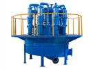
- Hydrocyclone Group
Hydrocyclone group is widely used in coal preparation plant...
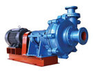
- Slurry Pump
Slurry pump is mainly used in mining, power plant, dredging, metallurgy...
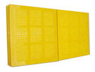
- Polyurethane Dewatering Screen Panel
In addition to the performance of...
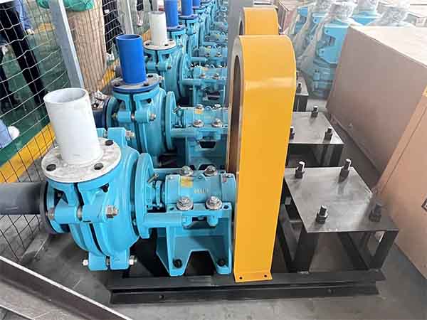
The Solution To The Blockage of The Slurry Pump Cavity
Date: 2022-03-04 From: Longding Author: admin
The slurry pump with a high concentration requires a large particle size. Alumina and coal slime often cause the pump cavity to be blocked during work, resulting in the frequent dismantling of the pump for cleaning, which seriously affects the normal work of the user and causes huge losses to the user. LZZG technicians believe that clogged slurry pumps often run intermittently. When the pump is stopped, the mud is very easy to dry in the flow channel of the impeller, and blockage will occur after a long time.
How to solve the blockage of the slurry pump cavity through technical design?
1. Under the condition that the main design parameters (flow, head) remain unchanged, the impeller is changed from the original closed type to the semi-open type impeller.
2. Redesign the hydraulic model.
3. Front guard redesigned to match newly designed impeller.
Impeller shape design
The situation of large slurry travel and easy drying and clogging is necessary to be considered. The width of the flow passage of the impeller is appropriately widened, the inlet is enlarged, and the closed impeller is changed to a semi-open impeller. The semi-open impeller is convenient to manufacture, low cost, easy to clean, can pump liquid containing suspended solid particles, and has little possibility of clogging.
The hydraulic design of the impeller
The semi-open impeller without a front cover eliminates leakage through the seal ring. However, leakage from the working face of the blade to the back of the same blade is produced, as well as leakage due to circulation in the gap between the blade end face and the front fender. At the same time, the hydraulic friction loss of the semi-open pump also increased slightly. Therefore, the hydraulic design formula of the closed pump can no longer meet the accuracy requirements.
Design of the front fender
Centrifugation of a semi-open impeller produces two forms of leakage, leakage from the back of the working face and backflow from the impeller outlet to the inlet. Losses due to leakage increase as the blade end face and forward fender clearance increases, and the clearance varies within a fairly small range. The front fender is designed to be inclined and parallel to the blade of the impeller on the axial projection, and the gap between the blade and the front fender is controlled at 0.75-1mm.
Previous:What Is The Difference Between A Slurry Pump And A Mud Pump?
Next:Structural Features And Advantages of Horizontal Slurry Pump
Leave a Message
Here you can submit any questions and we will get back to you as soon as possible. We will not disclose the information you submit to anyone, please rest assured.

Inquiry